
|
|
|
|
McPappy Racing Brushless Chassis Dyno The McPappy Racing RC Brushless Chassis Dyno version 2.0 comes in 3 different sizes, 2WD and 4WD, chassis testing or motor to motor testing, 4 different load levels, built in flywheel, can simulate an entire race, and with Windows 8 or later, can even be controlled with your voice. This can accommodate anything from a small slot car up to some of the 1/5th scales. Custom sizes are also available. Check out our video: Today's brushless racing introduced new variables: high timing with low rollout, low timing with high rollout, motor timing, rotor shimming, rotor diameter, gauss strength, gauss variance, gauss symmetry, sensor board symmetry, speedo timing, speedo RPM ranges, stator resistance, stator inductance, stator pole symmetry, epoxy and ventilation, bearing alignment, solder joints and wire resistance. The new McPappy Racing Brushless Chassis Dyno helps you to make sense of some of that. This dyno platform will allow you to test your car, buggy, truck, electric or gas motors against a brushless slave motor and flywheel that provides consistent resistance from test to test. The RC chassis dyno can provide different styles of testing:
The flywheel provides inertia resistance and the brushless slave provides constant resistance. Together they reproduce similar track resistance. The key component to this dyno platform is a huge piece of 1/4" 6061 aluminum which acts as a giant heat sink. Two large fans and all of that aluminum mass will bring the temperature of the motors and resistors back down to room temperature very quickly. This allows you to run many tests very quickly. To find your most powerful motor and speedo combination is actually quite simple. Your overall goal is to spin the flywheel and slave motor as fast as you can with the least amount of amp draw. The McPappy Racing Brushless Chassis Dyno can help you do just that. You will be able to find your strongest motors and most efficient combination of mechanical timing, speedo timing, RPM ranges, rollouts, and rotor diameters.
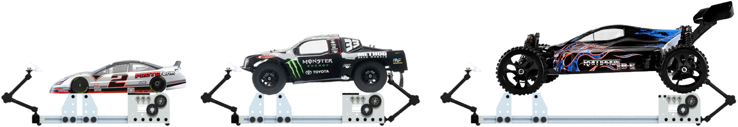
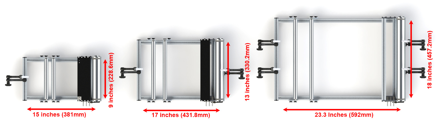
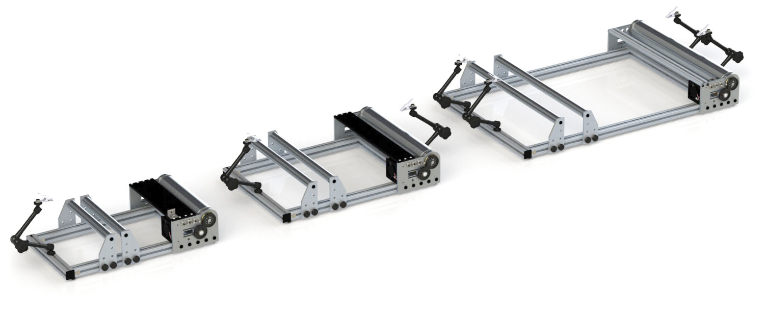
Chassis Dyno Sizes We offer 3 different sizes, and we can do custom sizes as well.
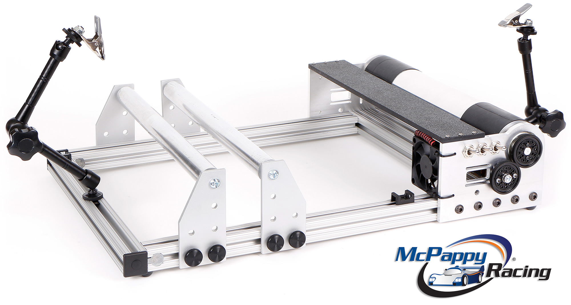
The frame is a T-slot extruded aluminum called 80/20. This allows for wheelbase adjustability and customization. You can attach parts like a LCD screen, toggle clamp, wire tie downs. We machined in quad anchor bolts in the corners to make the strongest 80/20 extruded aluminum connection. It's an open air design. Massive amount of aluminum will draw the heat out of the resistors and slave motor. This is important to keep the temperature the same so you get proper repeatable dyno results every time.
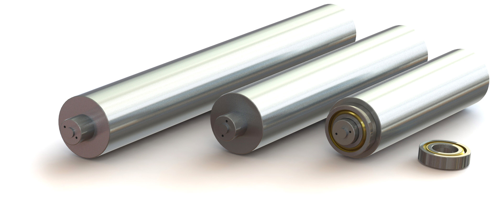
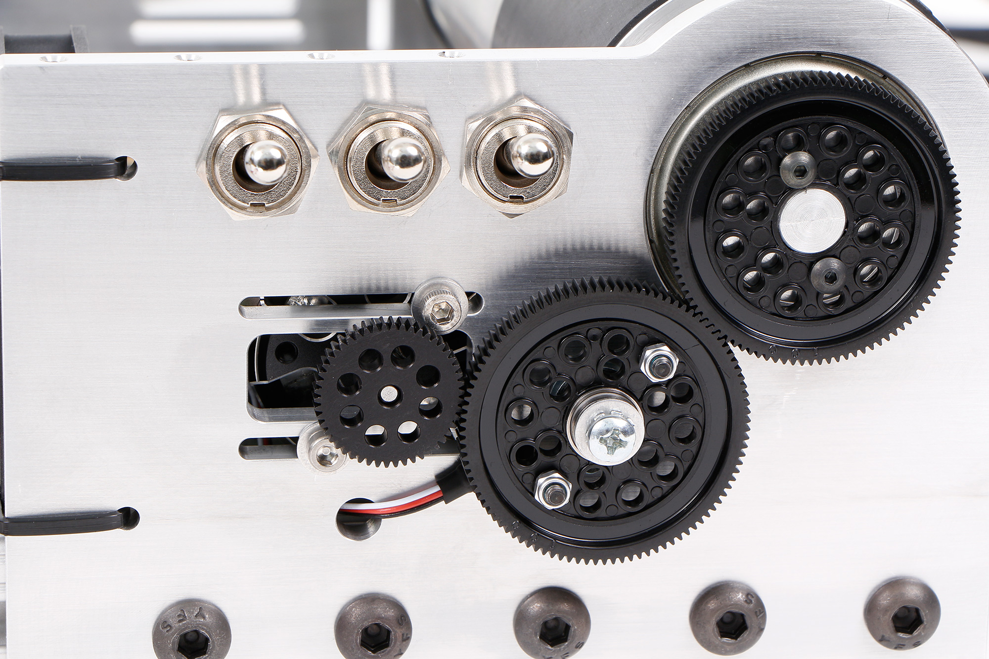
At the heart of the dyno we have a solid aluminum roller. It's a one piece design, machined on a lathe so it spins perfectly true. On the ends we have 2 inch bearings, each load rated for over 2000 lbs. The spur gear bolts directly to it. The entire width of the roller is usable so you don't have to adjust anything depending on the vehicle track width. And the roller itself is a flywheel. Even the 9 inch roller is over 4 pounds. This will give us great data on the initial motor pull and also helps to smooth out the RPM readings. Bicycle tubing makes for excellent grip and if necessary, is replaceable over the years. The front 4WD rollers are aluminum and also spin on bearings.
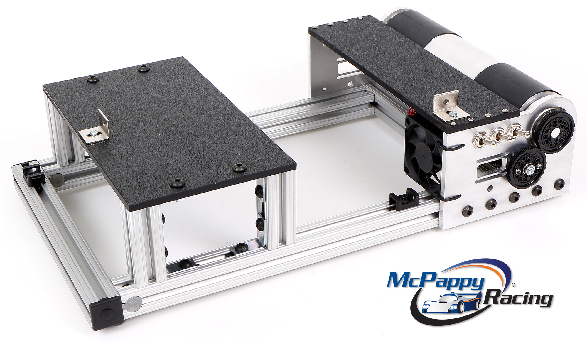
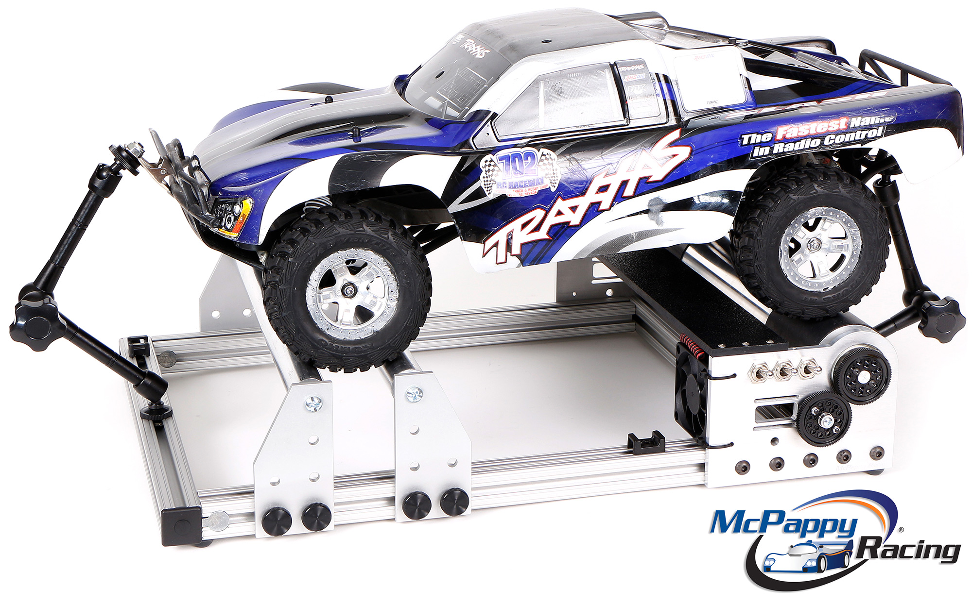
Chassis Dyno Testing Yes, no matter which size you want, you can choose 2WD platform or 4WD rollers. In most cases, the rollers can also hold a 2WD vehicle. Here is a picture of the 2WD RC dyno:
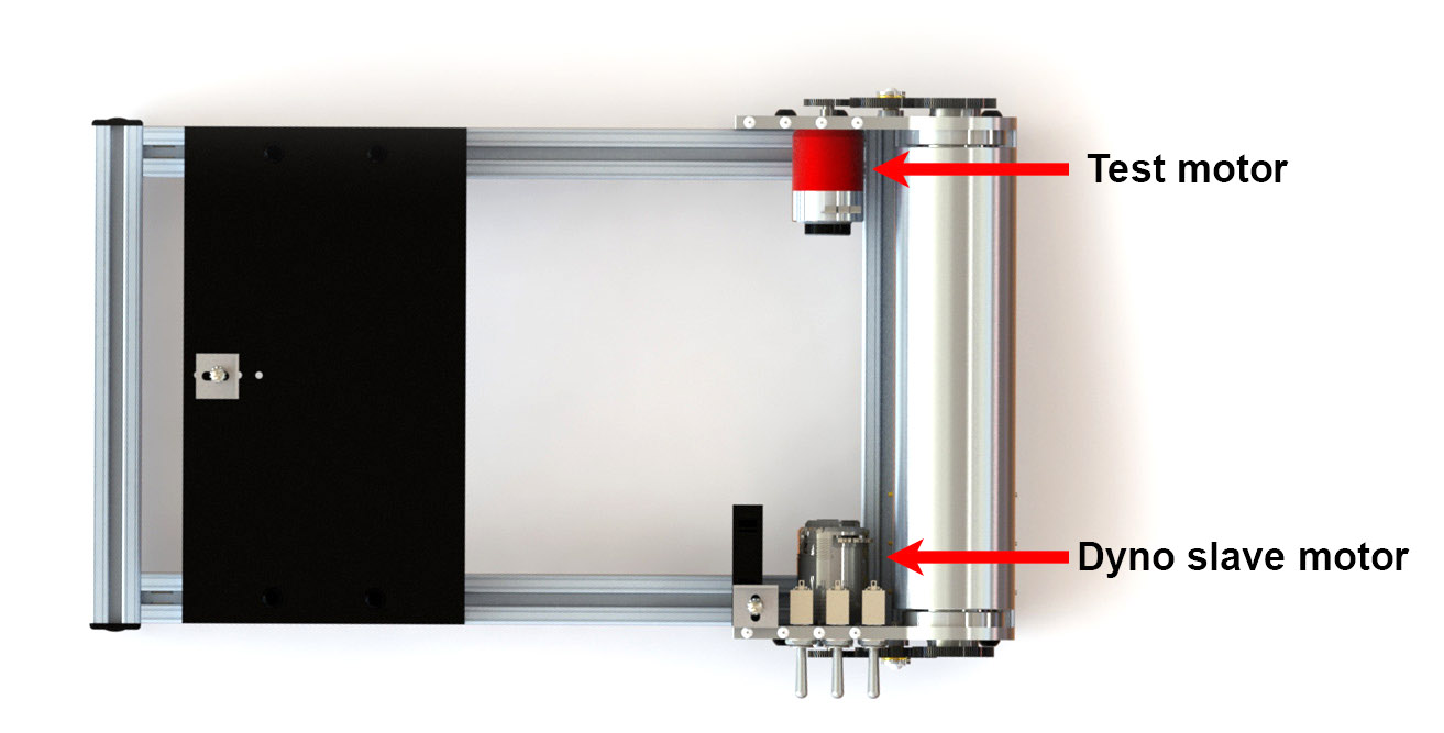
Motor to Motor Dyno Testing The left side is where your dedicated slave motor goes (21.5 is recommended but a 17.5 will also work). The right side was mirrored so you can add a 2nd slave for extra heavy resistance or if you want to do direct motor testing without your car or truck, you can do that as well. Our first chassis dyno also allowed for motor to motor testing, but required reconfiguring the assembly. Version 2.0 is much easier because you can bolt your test motor right on this side. For testing motor to motor without your vehicle, simply add your test motor to the right side.
Multiple Load Levels and Flywheel So why are flywheels and multiple load levels important? Because you can't determine power without a torque/controlled load. The definition of a dynamometer (dahy-nuh-mom-i-ter) is:
Both definitions reference the word torque or power. What is power? In regards to electric motors: Power cannot be determined by just RPM speed alone. It's RPM AND Torque together. Without load, you can make a motor's RPM's look better. But the motor's power most likely did not increase. A load is needed to actually determine if the power went up.
Computer Control and Voice Control For less than $100, electronics can be added to let the computer control the Nitro or electric RC throttle, load levels, and timing of when those load levels kick in. This offers addition benefits as the computer can do it exactly the same way every time and can even simulate an entire race. Watch our video for more details. With Windows 8 or later, you can even control it with your voice using a $10 program called VoiceAttack. For help setting up computer control, go to this page.
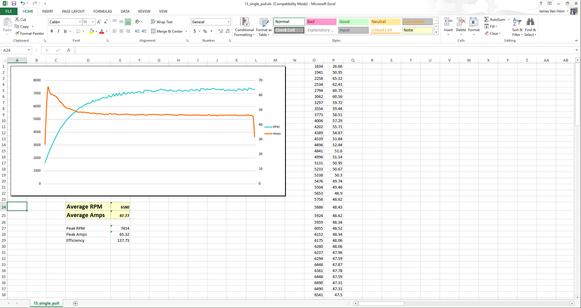
One Pull and Full Race Simulations For one pull, our dyno can using the combination of the 4 load levels and the flywheel to obtain excellent data throughout the entire power curve. We found a way to trim the beginning and ending data in the same way every time. Then the Excel spreadsheet will calculate the averages and efficiency based on all the data collected from the EagleTree elogger (up to 50 points of data per second).
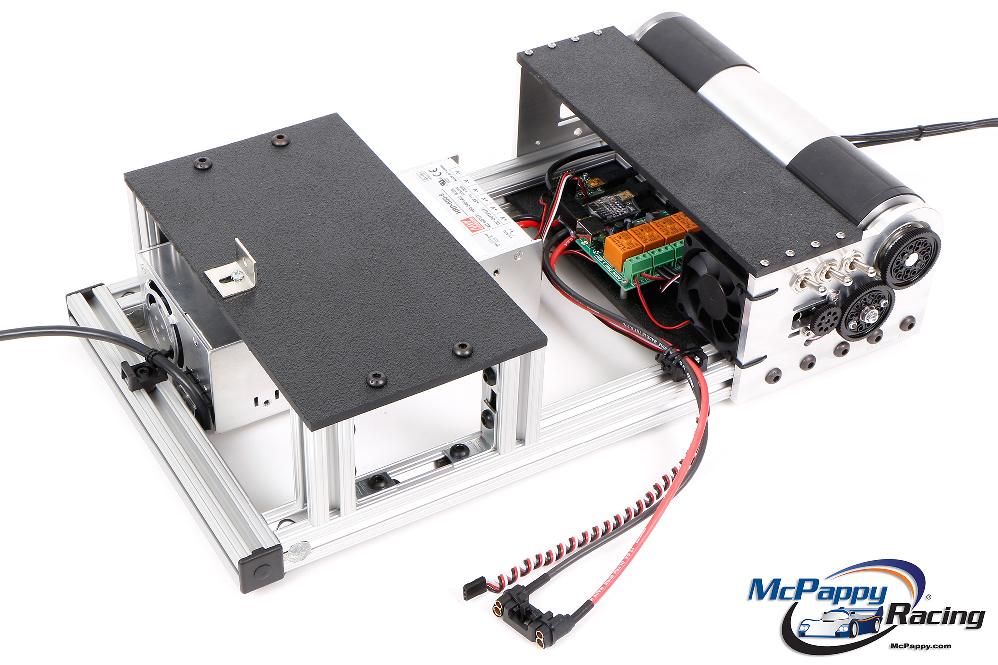
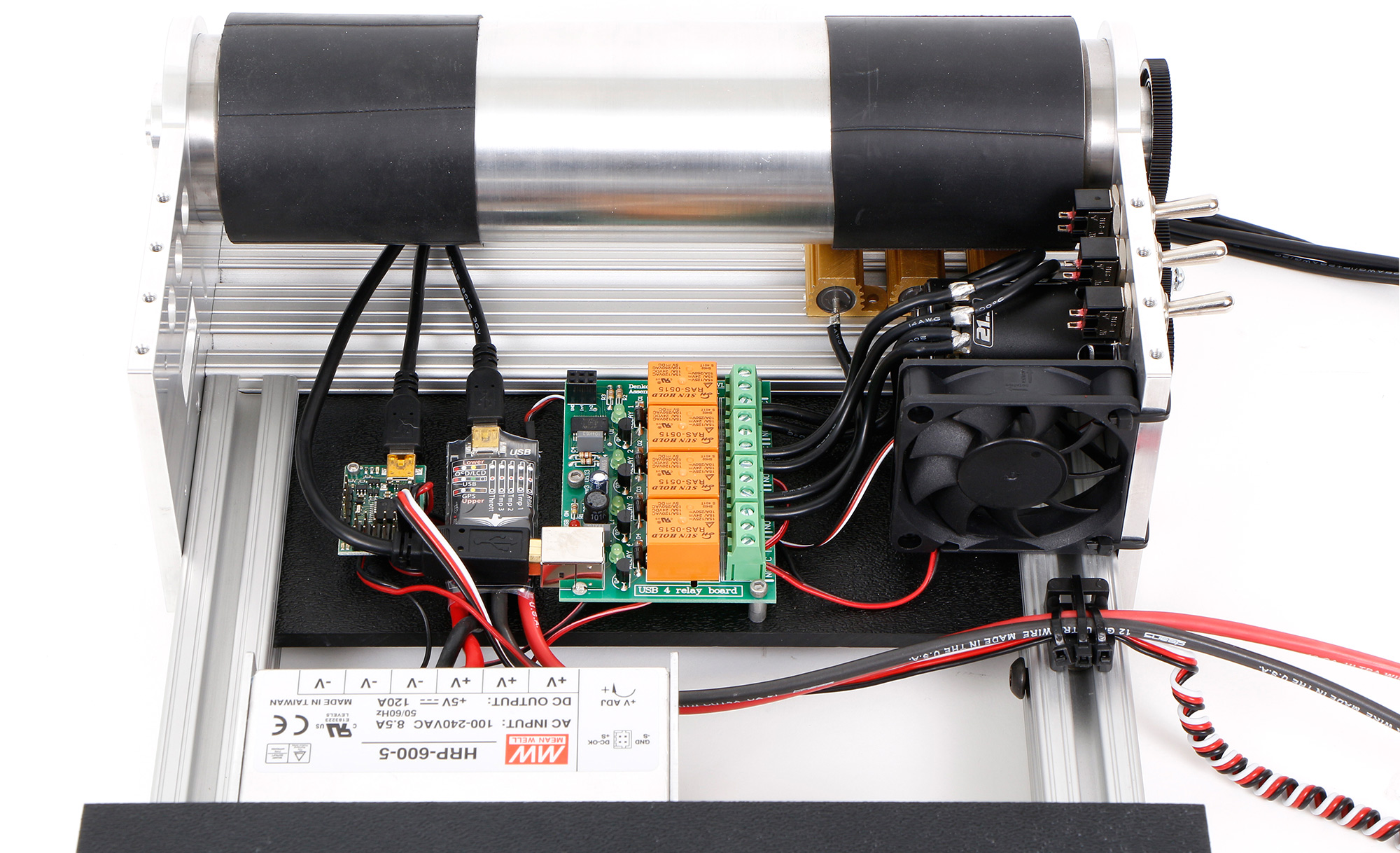
The computer can also control the throttle of the RC vehicle (gas or electric) and load levels to simulate an entire race. The benefit here is, it will weed out motors that overheat, which cannot be seen with one pull. Running the full race will reveal even more information. The dyno comes fully assembled and soldered up for 4 load levels with manual switches, resistors and a fan as seen in the picture below. All other electronics you will need to provide.
Included electronics:
Required electronics:
Example of a dyno loaded up with all the electronic goodies for computer automation and voice control. (Mechanical switches are not being used.)
Dyno Benefits Of course, the final testing will always be the track, but when all things are equal, a dyno can offer some benefits.
The overall goal is simple: spin the dyno as fast as you can with the least amount of amp draw. That will be your fastest and most efficient setup which will keep the motor cooler, leave more juice in the battery, and fall off less at the end of the race. Dyno your RC car, truck, buggy, puller, drag car and find some horsepower today!
Let us know if you have any questions !
|
||||||||||||||||||||||||