Overview
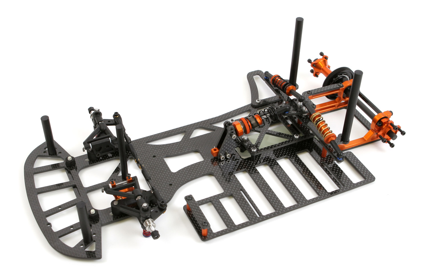
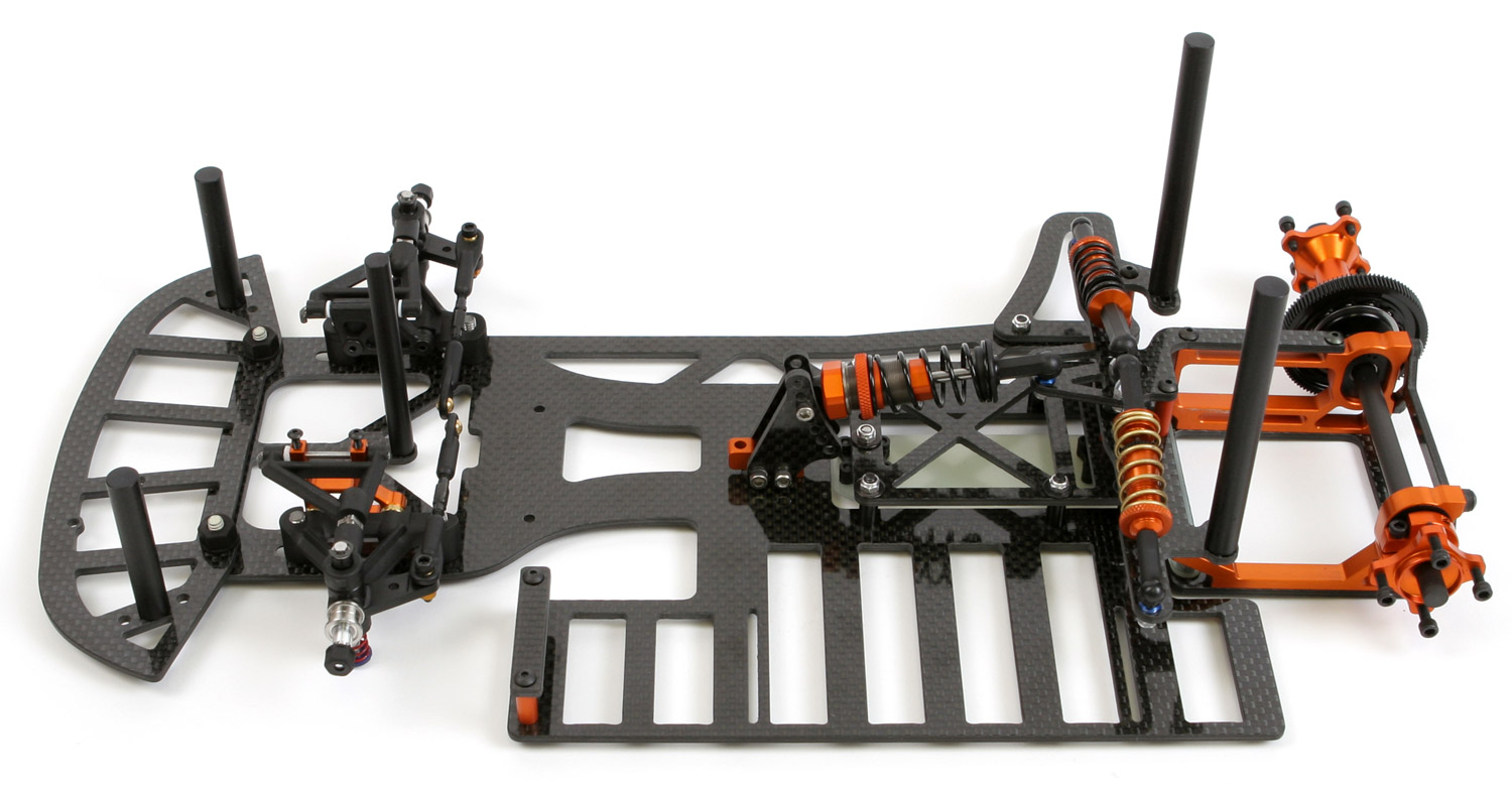
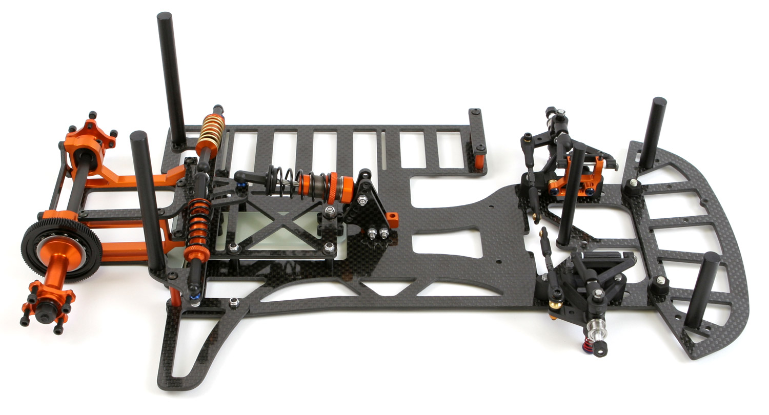
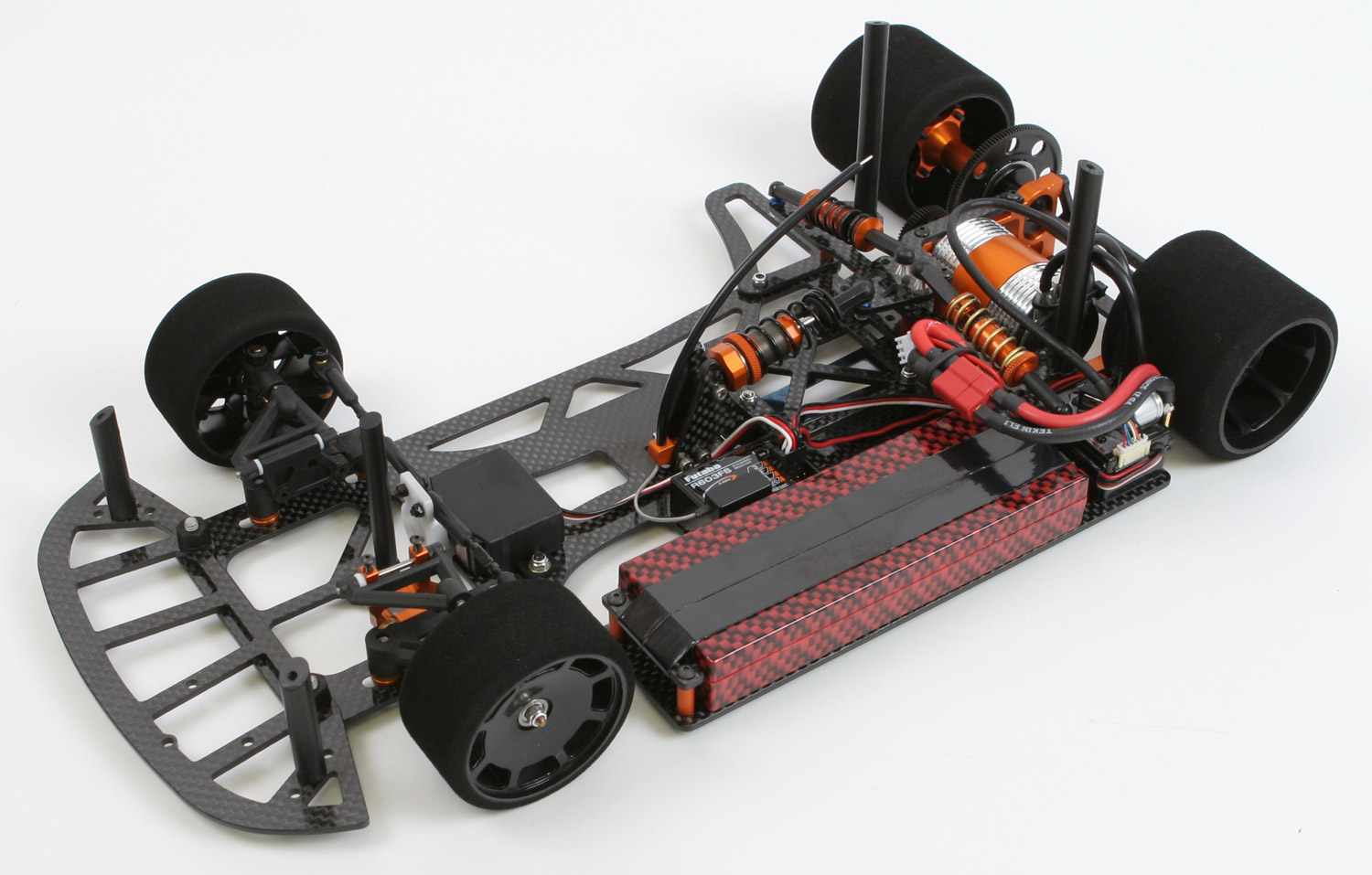
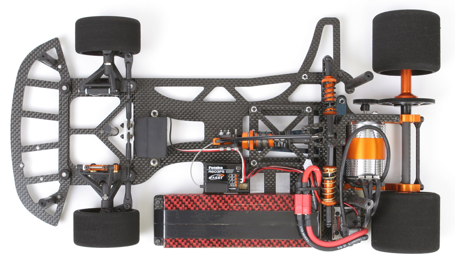
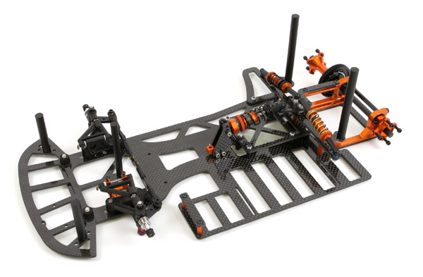
The new McPappy Racing 1/10th scale "Dart" has been designed with many new innovations. It has the left-most weight, lowest rear roll center, lowest center of gravity, roomiest rear motor pod, and lightest floating T-plate kit available today! The chassis was also designed and tested for just the right amount of chassis flex. The floating T-plate design not only offers centerline position, but also offers an offset position.


Carbon Fiber
All of the chassis components are made of 2.5mm quasi-isotropic carbon fiber. Cheaper carbon fiber is created with layers aligned in only two directions: 0 degrees and 90 degrees. We use quasi-isotropic carbon fiber, which means the layers are 0 degrees, 90 degrees and 45 degrees. This allows the strength to be higher and even in all directions. This allowed us to design it lighter with less material, and the flex will be consistent from kit to kit.
Bumper
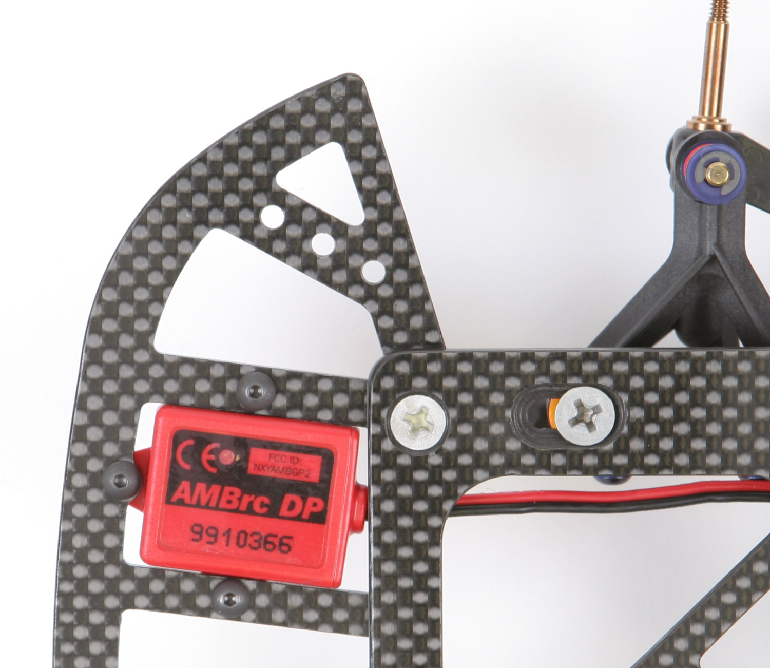
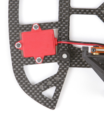
Working our way front to back, we designed a bumper that allows you to mount the transponder flush with the bottom of the bumper or chassis. This lowers the center of gravity. The leading competitor’s bumper uses a thin 0.84” carbon fiber material. We chose to stay with the full strength 0.97” carbon fiber material and yet our bumper still weighs less. Three body mount holes gives you choices on where you want to mount your Delrin body posts.

Delrin Body Posts
Yes, we didn't give you the cheap flimsy body clip style posts, we gave you machined Delrin body posts! The bottom of the post has been machined perfectly flat and a hole directly in the center. A hole exactly in the center means it's easy to change the posts or exchange bodies since it lines up in the same spot every time. While there are some adjustable body posts out there, these usually are aluminum or partly aluminum. The aluminum adds unnecessary weight. Compared to the aluminum/Delrin posts, posts made entirely of Delrin cut to the right height (we will show you how) are lighter and lowers the center of gravity.
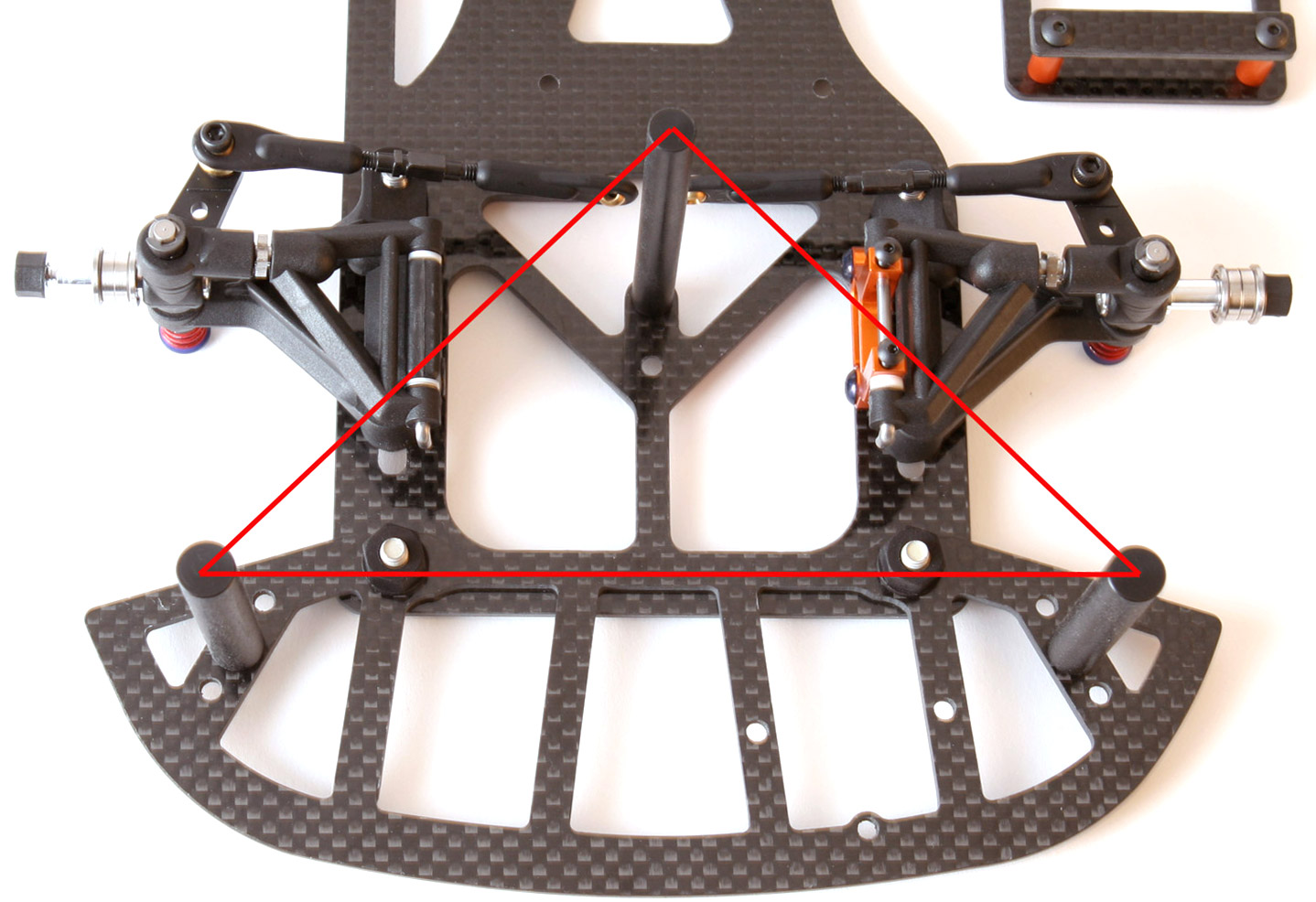
You’ll also notice that the center post gives you two center mounting choices more rearward than the competition. Having it moved rearward provides stronger mounting method due to the triangle effect of the front 3 posts. This allows the body shape to have less vibration and remain more solid when traveling over bumps or when receiving aerodynamic down force.

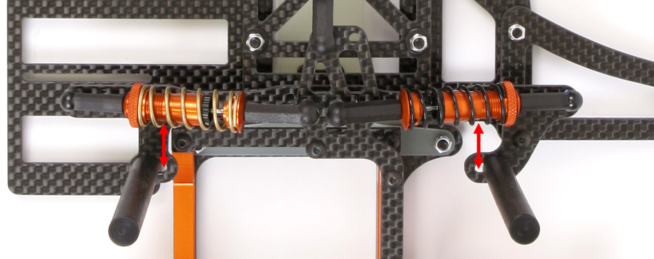
We also moved the rear body posts back further to allow for more body stability, less wing flutter, and ease of shock adjustment. Shocks easily clear the posts, and no problems getting your fingers on these shock collars!

Front End
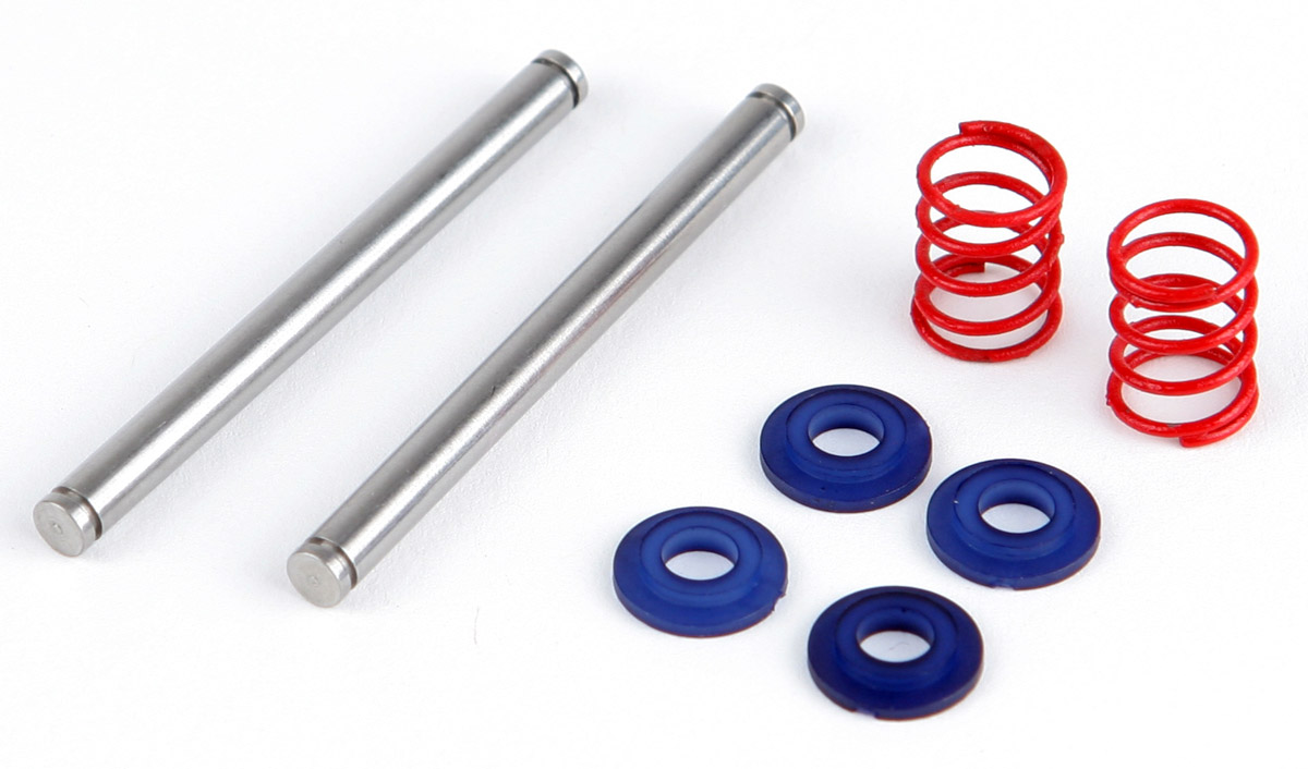
For the front end, we chose to use the Associated front end which has a proven track record. The only downfall to the stock Associated front end is the horribly short kingpins and rock hard 1/12th scale front springs. The stock kingpins are so short that the e-clips ride inside the upper eyelets and cause the front suspension to bind. So, we have included many improvements in the kit. You’ll be receiving long WindTunnel 1.5” kingpins, WindTunnel red front springs, and 4 spring buckets. Much better!

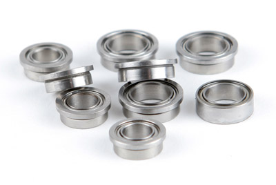
Boca Bearings
We wouldn’t give you some mystery no-name bearings either. You will be receiving Boca Bearings throughout the entire kit.
Adjustable Wheelbase
We’ve positioned the front end track width in the optimal position, but you can fine tune it with spacers on the front axles if desired. It’s more important to have an infinitely variable wheelbase length. So you’ll notice the slots run front to back offering any amount of adjustment you’ll need, including running the left front wheel more forward than the right front (this is a technique called “leading”).
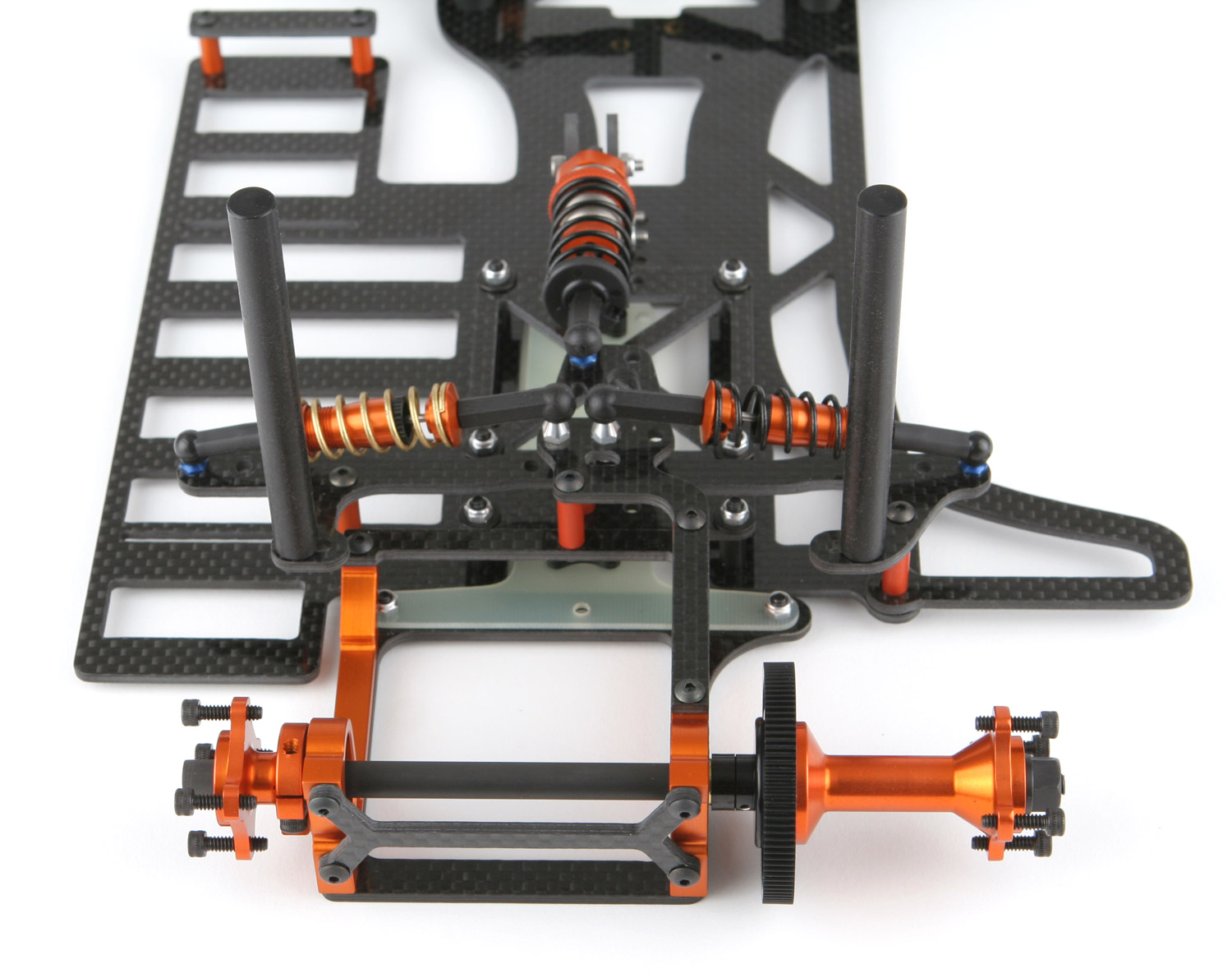
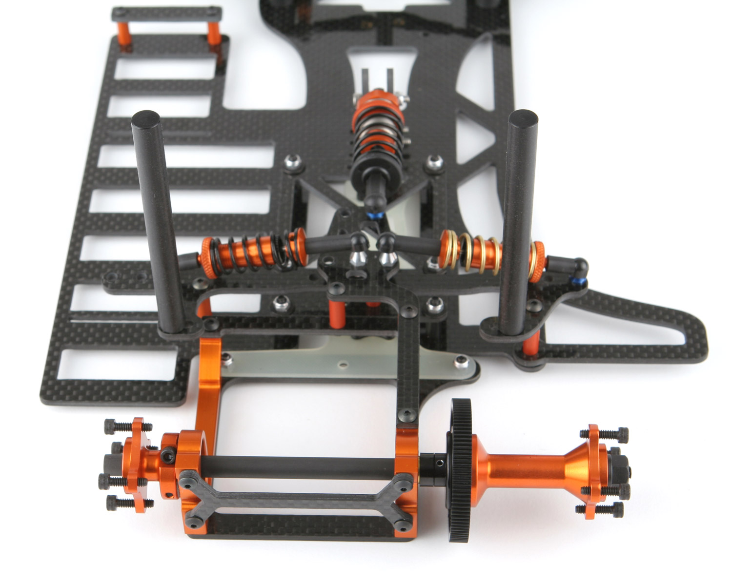
Offset / Centerline T-Plate and Pod Position
Not only do we have a floating T-plate design, but it's also adjustable. You can run the T-plate in the centerline or offset position. Although most situations benefit with the pod in the offset position, you can also run the pod in the center. Offset T-plate can be used like an "L" or "J" (purchased seperately). Here are examples of the 4 possible options.
|
Offset Pod / Offset T-plate Position
|
Offset Pod / Centerline T-plate Position
|
 |
 |
| |
|
|
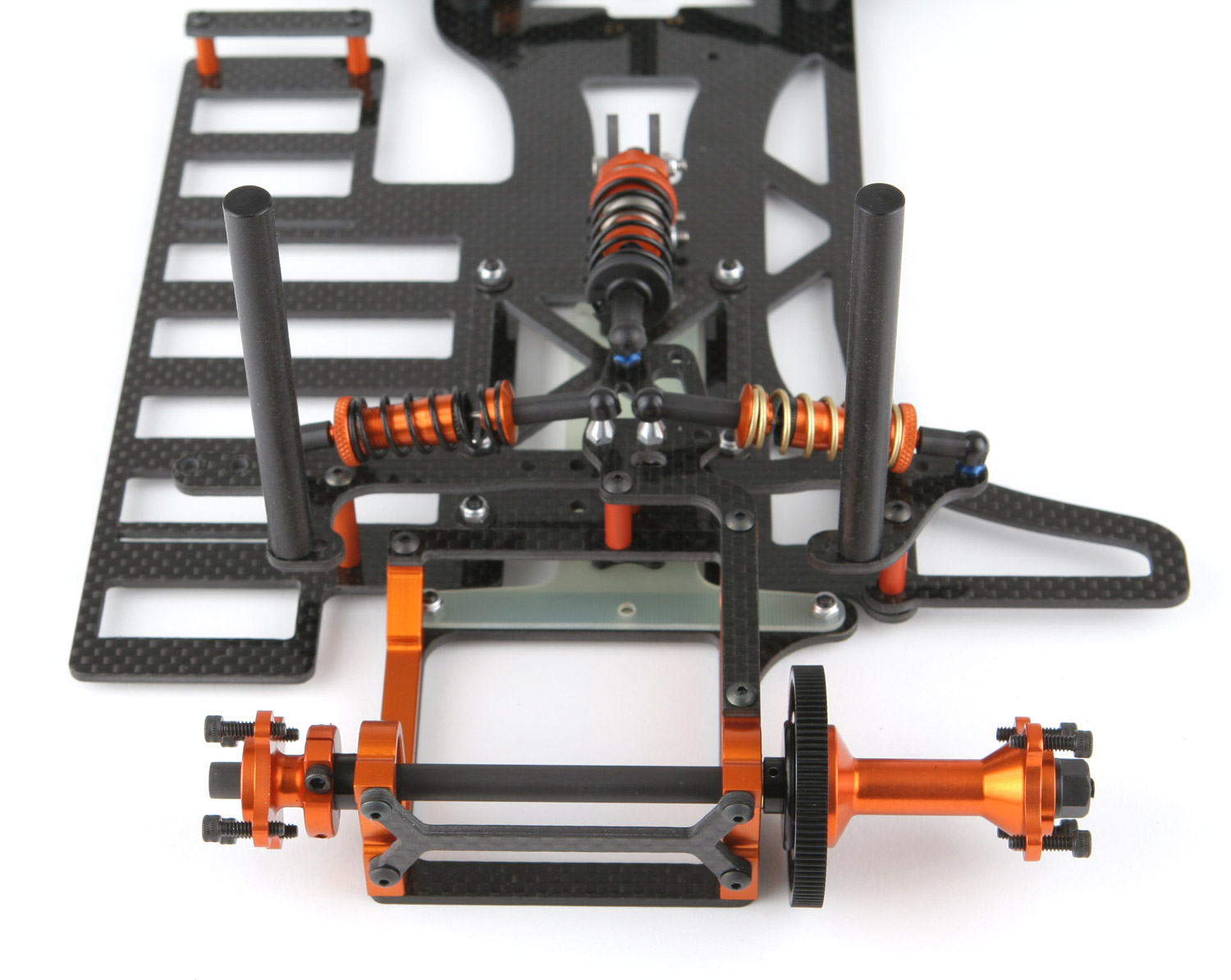
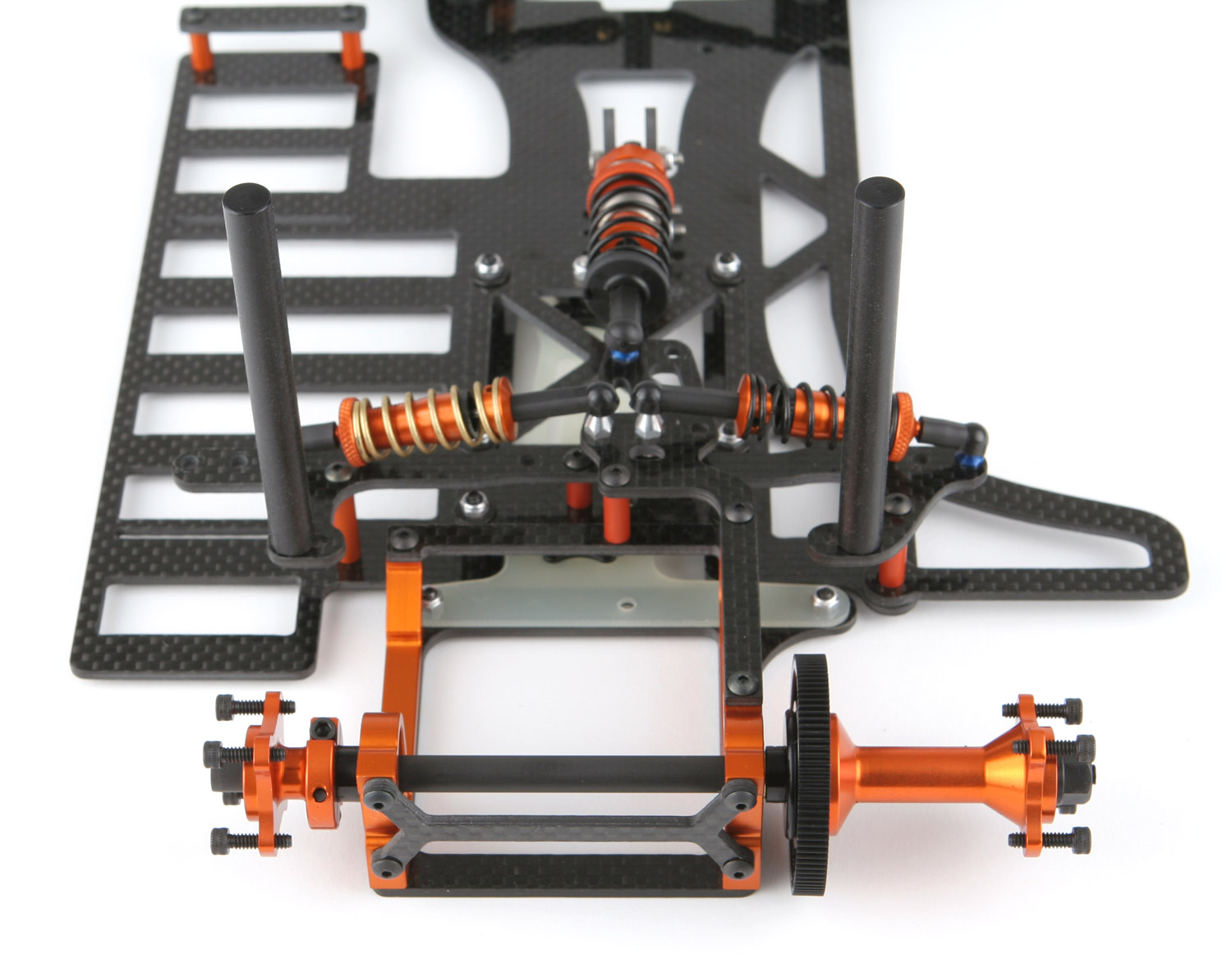
Centered Pod / Centerline T-plate Position:
|
Centered Pod / Offset T-plate Position:
|
 |
 |
Caster Block
We’ve designed a new lightweight caster block as well. Not only did we keep it light with a slightly lower center of gravity, but we included a little more threads than normal so you won’t have to worry about your 2-56 screw stripping out. In order to allow your right front tire to wear evenly plus maintaining a large footprint tire patch down the straight (to provide more control), you’ll end up running the right hinge pin in the lowest hole of the caster block. This is the same location as the plastic Associated 0 degree caster block. Since the plastic is lighter than aluminum, we recommend that you use the plastic caster block on the right side. Therefore we’ve only included a single aluminum caster block to use on the left side. If you still want to, you can purchase an additional caster block separately. They are universally designed and work on either side.

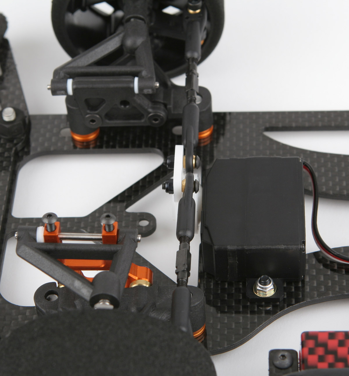
Ultimate Servo Mounting
There is a way to mount a servo flat while maintaining the perfect Ackerman and bumpsteer. Although you can drill your own servo holes for any servo (running flat or angled), we recommend the Futaba 9650 or 9602. The chassis comes pre-drilled to run the 9650/9602 servos flat. With the correct Ackerman, zero bumpsteer, and running flat, you reduce your center of gravity big time with this set up. Additionally, the 9650/9602 servos come with side mounting ears. This reduces the weight because we can eliminate the servo mounts completely as the servo bolts directly to the chassis! Have a look at the picture and you’ll see it doesn’t get any more efficient than that. We’ve included 4 Dubro ball links that help us to remove the bumpsteer. Just as importantly, there is less steering slop with Dubros when comparing to the traditional ball cups and ball studs. The techniques to remove slop from the traditional ball cups and ball studs can work, but at the expense of adding resistance. Dubros have less resistance and allow the servo to work easier and center correctly. We’ve even included shorter 1.25” turnbuckles to match the Dubro links perfectly, along with a cone washer (needed for the right side), and 2-56 locknuts. If you desire to run an angled servo, angled servo mounts and longer turnbuckles are also included in the kit.

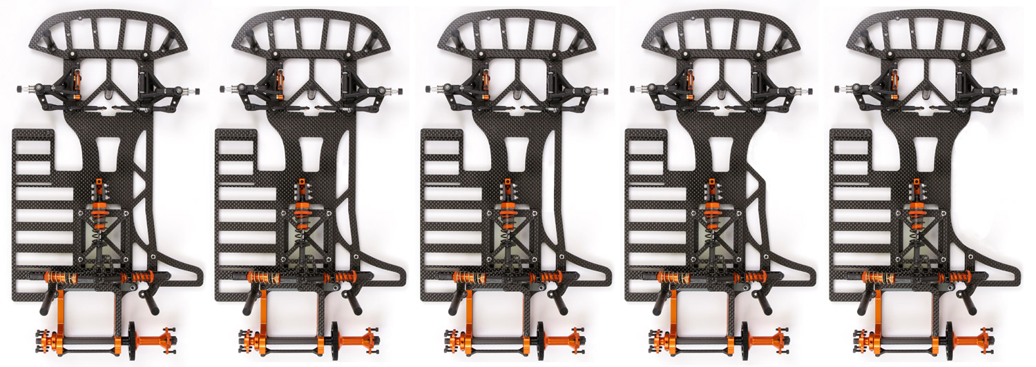
Flex
We spent a lot of time with 3D CAD displacement (flex) simulations and track testing to come up with the right amount of front-to-back and twist flexing for this chassis. We also designed the chassis so you can add your own cut outs to add more flex if desired. As seen by the examples, you can have 5 more variations of flex if you’re not scared of the Dremmel tool.

Batteries
The battery slots are moved out further to the left so you can get the most left weight possible. We also spaced the slots out properly to match today’s slightly larger diameter NiMH batteries. The batteries will be cradled with even pressure on all edges of every cell, and they will sit at the correct ride height.
LiPo Mounting System
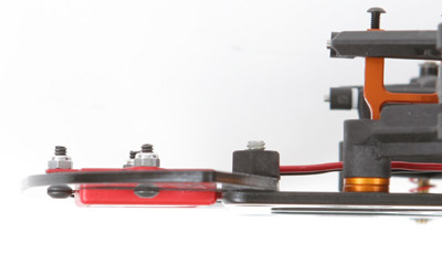
If you plan on running LiPo’s, you may be pleasantly surprised at our LiPo strap retaining method. Although you can use tape, we wanted to offer a retaining system that uses a screw down method for the convenience factor. The competition uses 4 standoffs with 2 braces. The downfall to this method is the standoffs move your LiPo battery inward towards the center of the car. We came up with a method that holds the LiPo all the way out to the very edge of the car for maximum left side weight. We also did it with half of the standoffs, braces and screws. Additionally, the two standoffs are lighter since they are shorter, and the single LiPo strap brace is positioned lower than the top of the battery for a lower center of gravity. With only two screws, simply screw down the LiPo strap into the standoffs. This pulls tension on the retaining strap keeping everything solid.

The tape you see in the picture is not sticky. It’s been doubled over so there is no stickiness exposed. It’s being used as a retaining strap only. Since the sticky side is not being used, it’s reusable too.
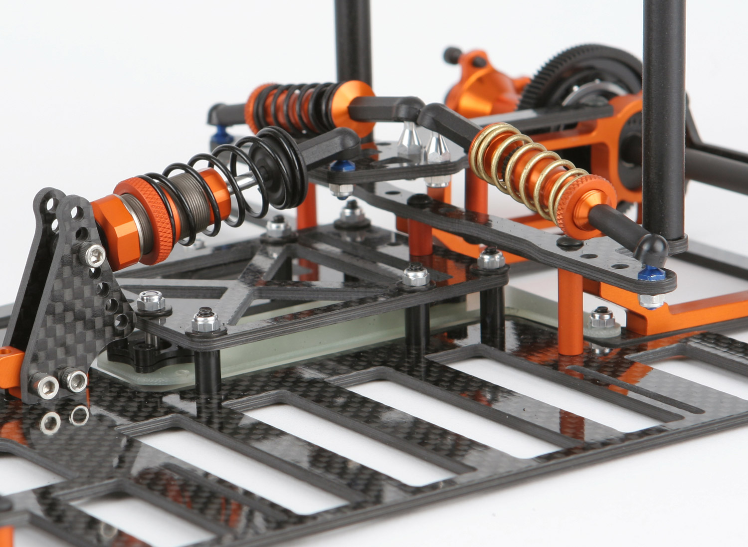
Center Shock
For the center shock, we chose HPI’s newest center shock. It was the lightest and also had the least amount of piston slop compared to the others. The e-clips hold the piston securely. The latest version has a few new design improvements. Instead of a double O-ring seal, they now use a single O-ring in combination with a plastic retainer. This helps to reduce the friction on the shaft while retaining a superb seal. Those components are now encased by a new housing that makes it easy to assemble or perform maintenance. The shock cap has also been redesigned with edges to provide a better grip. The shock still used the bladder for the ultimate in consistency. The shock is made out of 7075 aircraft aluminum. We removed the purple anodizing and anodized it our “Beryllium orange” to match the rest of the kit. Click here to learn a little more about the specific orange we chose.

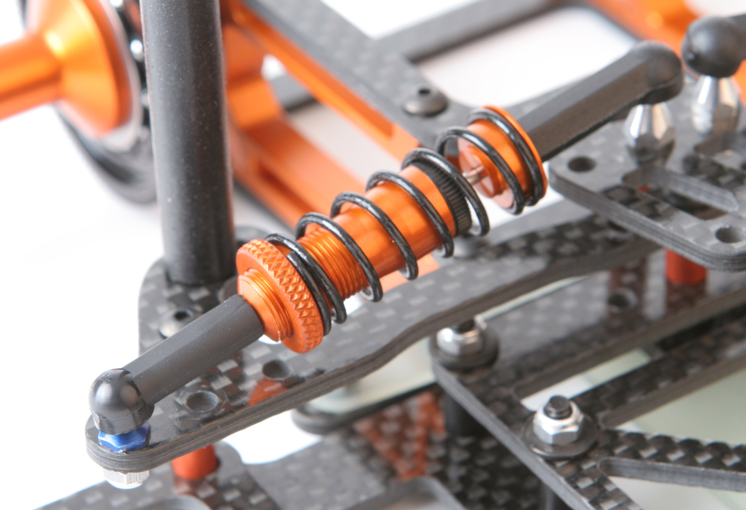
Side Shocks
For the side shocks, we went with IRS Top Gun threaded VCS shocks (thanks Dave!). IRS designed their own foam cup and one piece piston. The threaded seal works so well that you can usually go for months without maintenance (and the oil usually drains clear). The spring retainer has set screws on both sides which allows the retainer to stay perfectly in line with the shock shaft. No more crooked springs and retainers! The shocks are made out of 7075 aircraft aluminum. There really isn’t much that can be improved here, so that’s why we chose IRS side shocks. The side shock angle can be adjusted for a more linear or progressive feel using 3 different ball stud heights (medium and long ball studs are available separately).

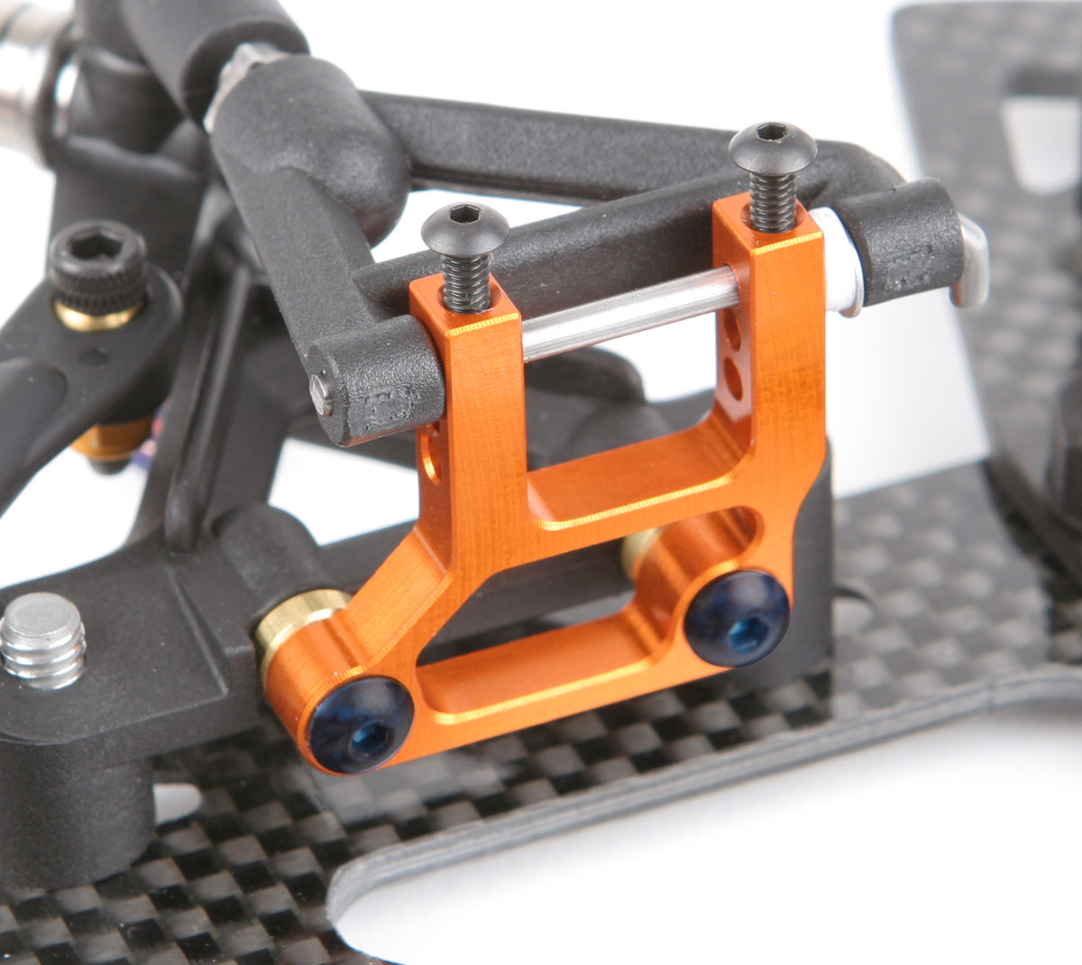
Floating T-plate
The major reason that the latest chassis from the “leading blue competitor” is doing well is the floating T-plate design. This allows the pivot ball to be lower which reduces the rear roll center. Our new "XXXX" pivot ball and pivot ball socket design has a much lower rear roll center than anything available. It's also has the largest range of rear roll center adjustability. Our new floating T-plate design is also the lightest. We used a lighter carbon fiber bridge instead of aluminum.

Low Rear Roll Center
So why is a low rear roll center so important? What are the benefits of a really low rear roll center? For starters, it allows the rear pod to roll easier, in both directions. This makes for a more efficient rear suspension. Your side shocks, oil, and springs will receive more activity and be more effective because there is less pivot resistance (not referring to friction) in the rear suspension. The second major benefit of an ultra low rear roll center is more left weight in the corners. You can scale a standard T-bar car and a floating T-bar car and have identical 15.5 oz on the left rear tire. It would seem like they would have the same weight on the left rear in the corner. But the car with the lowest rear roll center will keep more weight on the left rear in the corner. On the other hand, a high roll center will not allow the chassis and rear pod to roll independently as easily, therefore the entire car rolls when it goes into the corner. Weight comes off of the left rear tire. That’s bad! So low roll center fixes that.
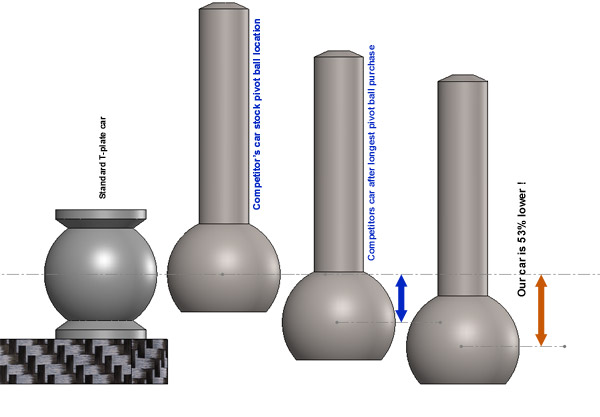
Lowest Rear Roll Center
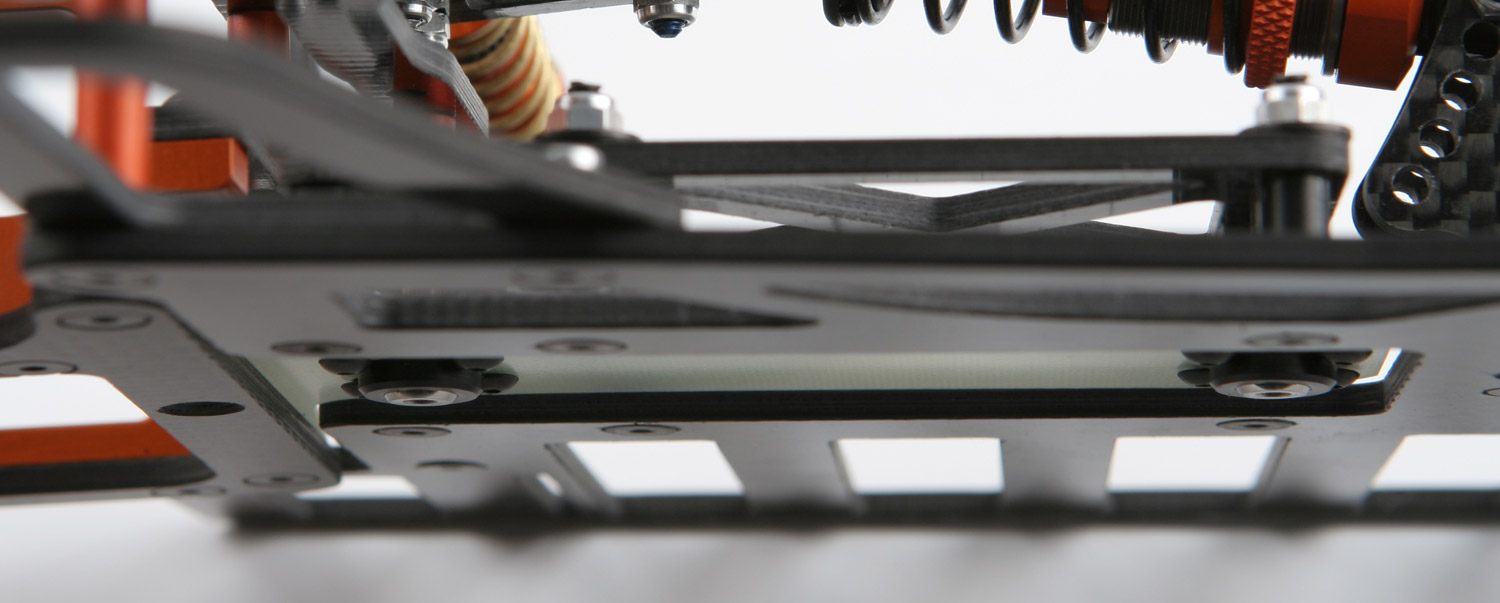
A standard T-plate car’s rear roll center is 0.1435” from the top of the chassis. The leading competitor’s floating T-plate kit’s roll center is actually the same as a standard T-plate car. If you purchase their longest pivot balls, the roll center is lowered to 0.0370” from the top of the chassis. This lowers the roll center by 0.1065”. With our combination of custom pivot balls and custom pivot ball sockets, our roll center is so low, it’s actually -0.0195” (below the surface) which lowers the roll center 0.1630”. When our competitor’s kit is at its lowest, our kit is still 53% lower! Click here for a video of how our pivot ball sockets are machined.
It’s important to note that the T-plate height does not determine the roll center, the pivot ball does. It's hard to tell from the above picture, but our pivot ball is actually flush with the bottom of the chassis! Viewing the diagram below, you can see how low our roll center is.
The end result? More rear grip. And more importantly, a much better version of rear grip! Since the left rear tire is now providing more traction in the corners, you now have more stability and consistency. As a bonus, the left and right rear tires will wear more evenly. So what will you do with all of this new rear grip? There are many options, but the most dramatic would be: you can reduce your rear spoiler or wing down force for more speed. You could also go to an exotic rubber family of tires which produce less grip, but are lighter with less rotational mass. Or keep it all and you’ll be able to safely add more front grip (which is much easier to do). Your car will turn like it’s on rails!
Crossbrace
To save even more weight, carbon fiber and standoffs were used for the crossbrace. To match the rear pod, everything was lowered. All 3 shocks are lower than any other car. To provide more body mounting options, we included side to side slots for the rear body posts.

Nerf Wing
You’re probably thinking, “What could you possibly do to a nerf wing to make it worth mentioning?” Well, do you ever get black stuff under the bottom right side of the chassis? Nerf wings don’t usually rub on the ground since they sit higher than the chassis. So we extended the nerf wing longer than average, so that we could make the chassis narrower on the right side. This gives us two benefits. First, it allows for a little more side to side motion with less chassis rub. Secondly, it saves weight having a narrower chassis.
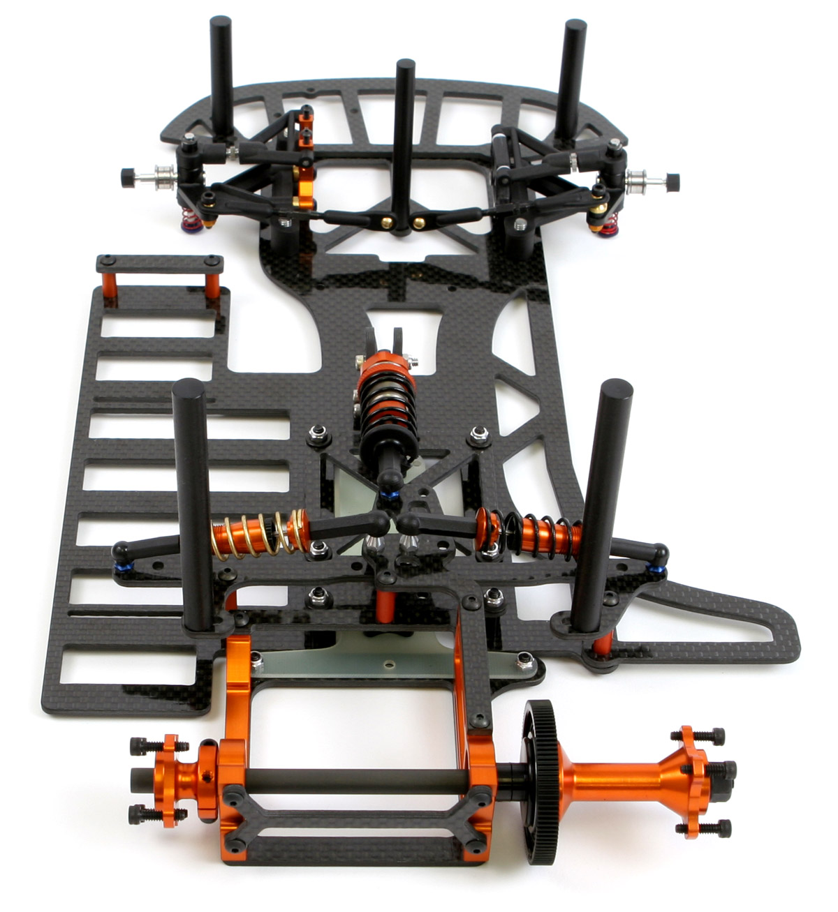
Topless Motor Pod Design
There was nothing available on the market that could do everything we wanted, so a fresh design of the entire pod was the proper solution. A completely open top plate design allows for easy motor swapping. No more need to take your pod apart in order to get the motor out! No problem using any type of motor heat sink either. There’s plenty of room.

Lowest Center of Gravity
A front pod brace and rear dogbone brace makes the entire pod rock solid. Essentially, we moved the top plate material down to the front and back of the pod. This lowers the center of gravity. To help further, the small remaining top plate was also lowered more than everything else available. This allows the center shock to be even lower as well. Speaking of lowering the center of gravity, we made sure the motor sits perfectly flush with bottom of the chassis. It’s surprising how many cars kits don’t do this.
Easier Brushless Wiring
The motor mounting was positioned so that the solder tabs are straight up and down. This makes the wiring easier and keeps them away from the tire and body post.

Roomiest Motor Pod
One of the biggest improvements was the amount of room for motor movement. This pod gives you more room than any competitor (and we didn’t extend the wheelbase to do it). You can fit a 65T pinion with a 124T spur gear with some room to spare! Bigger pinions and spurs allow for a more efficient gear mesh. Brushless motors really seem to benefit from this. Another benefit of moving the motor forward is it reduces the pendulum effect. Having too much rear weight near the rear axle can cause the rear end to keep swinging outward in the corners. Moving the motor forward helps to reduce this effect.

Did you ever think you could fit a Novak heatsink laying down? Removing the inner "V" from the heat sink would provide even more room.
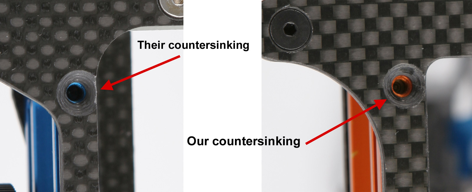
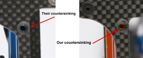
Rear Steer Bottom Pod Plates
Rear steer slugs with panhead screws require that you raise your ride height up in order to pass tech inspection. Since slugs are usually made from aluminum, they add a little weight as well. The optimal solution is to offer various rear steer pod plates with countersunk flathead screws. However, it’s not a good design to have these countersunk holes right near the edge of the carbon fiber. This is a weak spot in the design. So we designed a way to position the screws so that the countersinking never comes close to the edge of the carbon fiber.
The kit comes with a typical 0.0 degree plate, but 0.5 degree and 1.0 degree rear steer plates are available.
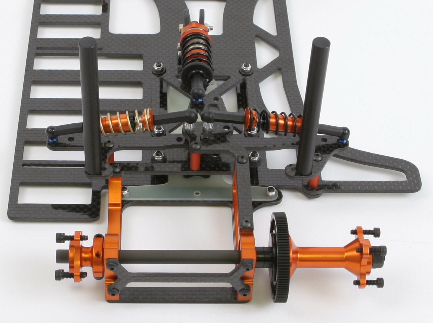
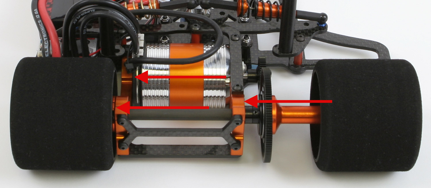
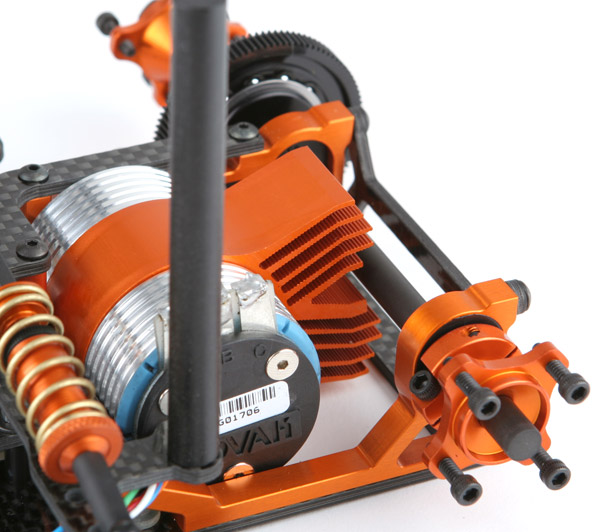
Left-Most Pod and Motor
Unless you are running large Veledrome sized tracks, you’ll find that getting your weight to the left as much as possible will help many things like improved left side tire wear, increased traction, reduces excessive roll, etc. In most cases, offset pod is today’s choice for most racers. So we improved two things. First, we moved the entire pod to the left as much as possible. Secondly, we moved the motor (within the pod) as far as possible. In the picture below, notice how far left the motor is. The pod and motor are more to the left than anything available.

Lightweight, Left weight, and Low Center of Gravity
You may have noticed a theme throughout the design. We've designed everything lightweight, we moved the weight to the left, and we moved it low. There are some racers who don't think the location of weight matters much. They don't care if their car is heavy throughout since they have to make weight anyway. I often give them the analogy, "If you don't care where your weight is, then put a rigid fiberglass rollover antenna on your car with your lead weights at the top. I'll put my weight low and left. Now let's race and see who can turn better."
Tungsten
Having a lightweight car throughout allows us to use more weight where we want it. So we designed the car from the beginning to use the ultimate weight, tungsten. The word tungsten means "a substance of high density", and is
derived from the Swedish language, "tung" (meaning "heavy") and "sten" (meaning
"stone"). It's an appropriate name as tungsten is a metal with one of the highest densities. Tungsten weighs 1.7 times more than lead! Only gold, platinum, and a few other precious metals have a similar
density. Tungsten is also completely non-toxic and environmentally friendly. It's a really hard metal, and will last for years. It's a nice one time investment.
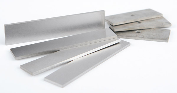
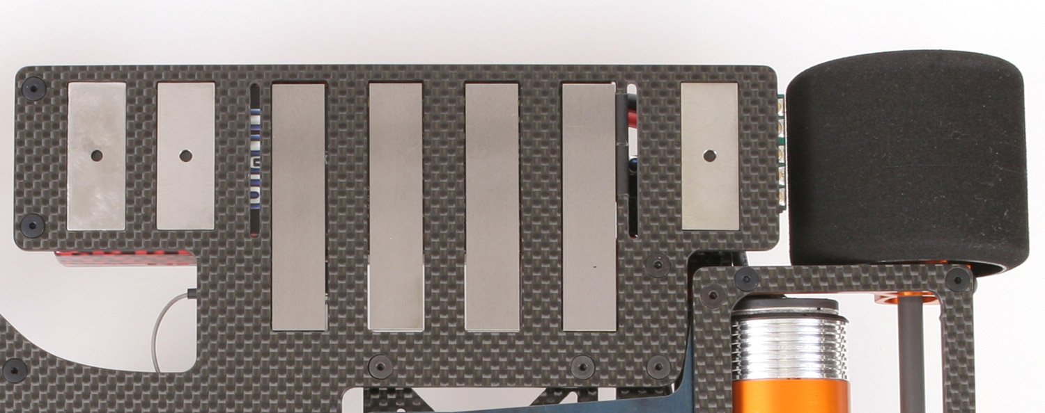
It does not look like it, but the 7 tungsten plates in these pictures weigh a whopping 4.77oz! You can see that we designed the plates to fit exactly into our chassis. No more need to put lead on top of the chassis or components. Since LiPo's take up most of the left side, most racers have been placing their lead inboard towards the center. With our new chassis, the tungsten plates fit UNDER the batteries and electronics! It's flush with the bottom of the chassis. You can't get weight any lower and more left than this. Not only does this lower the center of gravity, but the plates are also used to lock the LiPo battery in position. The LiPo can't move at all with these plates servo taped to it. These tungsten plates are expensive, therefore they don't come in the kit, but they are available separately.

Let us know if you have any questions!
Click here to order.
|
NOTE: Pictures with electronics in them show some items that do not come with the kit.
|
|
Copyright © 2021 McPappy.com. All rights reserved.
"McPappy Racing" name and logo are Registered Trademarks.
|
|
Product of Web Wonderland, Inc. Made in the USA
|

|
|